The “Not So Simple Guide” to choosing resistors - Part 3
Understanding power dissipation on resistor datasheets.
Hi fellow Electronics Engineers.
Note Let me state for the record, I wish to make no illusion about the field of engineering. If you genuinely wish to pursue design engineering, as a rewarding career, you will need to develop (if you haven’t already) both a strong ability in maths and a passion for physics. However, I believe, that today’s society has so much untapped talent, who have been scared away by academia, as those individuals have school results that are not in the top 1 or 2 % of academic achievement. Many of these students believe they do not have a place at the table of engineering. This, in my opinion, must stop immediately. Industry is (and it will only get worse) in dire need of an army of worker bees. From my experience the backbone of industry is seldom Ivy league university folk. Fundamentally, If the services and products our engineering community develop is primarily from the 1% or 2 % portion of society, who were fortunate enough to come from an Ivy league institution, then due to homogeneity, we will stagnate at a societal level. We must encourage and embrace all those who whish to join us, and I mean all ( including the 1% or 2% people). If someone tells you that you can’t, prove them wrong and show them that you most definitely can!
Now let us continue from the previous blog, where we discussed ‘How to choose resistors based on physical properties and intended manufacturing methods.’
For now, I would like to continue the same thread of how to select a resistor.
Calculating power
Just a quick reminder, the unit of Power in SI (international system of units) is the Watt and it is equal to 1 Joule (the SI unit for energy) per second. A Watt is basically the amount of work done per unit of time.
Note The observant amongst you will notice the words Watt and Joule have their first letters in capital letters. That is because these words are named after famous scientists. Yes, there was a Mr James Watt, he was an inventor whose steam engine was essential for the industrial revolution. Also, there was a physicist called Mr James Joule. However, there was no Mr Kilo nor a Mr Gramm/e (not that history assigns acknowledgement too anyway) so we don’t write capital K we write lower case k, for instance kg not KG.
I freely admit that so far in this blog series, I have shied away from giving you Ohms Law. However, just to make sure you have a source at your fingertips, I remember when I first started my journey as an electronics engineer, I found this style of graphical representation very useful.

Mastering the transposition of Ohms Law should place you firmly on your path to developing the skills necessary to calculate what the power dissipation of components in your application circuits is.
In due time you will also learn how to use more advanced analysis methods like Kirchhoff or Thevenin equivalent circuits, or maybe a simulation package may aid more complex circuits. However, these more advanced analysis techniques are the subject for future blog(s), and I would not recommend you attempt to understand these techniques before you have a comprehensive grasp of Ohms Law. Also, I would encourage you to not solely rely on simulations, it’s important that you understand what the simulation output is attempting to convey, after all, Garbage In Garbage Out (GIGO).
Note: Power is mostly dissipated as heat in a component. Power is NOT consumed! Cake is consumed. Power, by the law of energy conversion (yes physics is fundamentally important), can neither be created or destroyed, it can only be transformed into another form of energy. Therefore, anyone who asks you what the ‘power consumption’ of a component is fully deserves an eyeball rolling!
Selecting a components power rating
From the working example above, we now know we require a component with a minimum power rating of 8.7 mW.
Hopefully, by now you have grasped the power the component is dissipating will (mostly) be dissipated as heat and before we can say what the power rating of the component will be, we must consider what temperature rise we want the selected component to be capable of operating with.
To understand what the target temperature should be, you may want to consider the following: -
A) What the maximum ambient temperature of the overall assembly is.
B) Internal heat rises caused by the dissipation of local components (maybe not on the PCB you are designing, but inside the same chassis).
C) If there are any maximum component operating requirements for the design.
D) If you have a maximum temperature difference delta (∆) of any component.
Here’s some advice where you may be able to find answers to consider.
A) The maximum ambient temperature is normally given to us as a requirement or maybe relates to some industry recognised standard like ETSI or MIL-STDs (the subject of future blogs). i.e., electronics that operate in the home often are specified to work across the temperature range of 0 °C to 40 °C. However, some aerospace designs need to work from -55 °C to 125 °C.
B) A basic method for this is given in the example below. More advanced methods include dedicated thermal simulation software (more to come in the future).

C) Quiet often there may be a need to keep a component temperature below a limit. For instance, the circuit you are designing may be specified to work up to 40 °C. However, if it is a hand-held device (think smartphone) and when you turn it on, the device self-heats to 80 °C and causes 1st degree burns, do you think that is acceptable?
B) The operating temperature is intrinsically linked to how reliable that component will be. More to come in future blogs, but the life of a component is halved for every 10 °C.
As a starter for 10, considering the above points you may think this design you are working on, has to work on an office desktop (or lab) so up to 40 °C ambient sounds ok. Then the components around it (heatsinks, or maybe fans on etc) mean the component could be 50 °C before any power is dissipated. Finally, everything considered you don’t want this component to get hotter than 15 °C delta.
Back to the example resistor calculation where we had to manage a power dissipation of 8.7 mW. Reality is for a 1/4 W rated resistor operating at room temperature you are on a home run. However, if this was a 100 Ω, then that would be 1 W of power. It should be obvious that attempting to set a resistor to 4 x overstress is unacceptable, in this instance you would be required to fit a resistor with a larger power rating.
Note: do not attempt to put 10 volts across a 100 Ω 1/4 W resistor! If you do, you'll quickly see it start to smoke. The smell is very distinctive. Also, if you ignore the previous advisory, please don't hold the resistor in your hand while you do this! If you are the kind of specimen that ignores both advisories, then I suggest we let Darwin sort you out.
Selecting the correct power rating for your design
As an example, let’s attempt to finally nail down the power rating of the component for our resistor. Below is an extract from a resistor datasheet: -
Let us start with an example of a typical manufacturer ‘standard electrical specification’
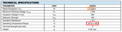
The first highlight is orange, the manufacturers offer a 0.25 W resistor. Great start!
Second highlight in red, this component works all the way up to 165 °C. Therefore, you think your job is done and you are done with respect to thinking about power. If you were looking for a resistor that needs to dissipate 8.7 mW, then I would tend to agree with you.
I would always encourage you do a stress analysis (to be discussed in a future blog). Therefore, assuming you want to be thorough, I will attempt to take you through to the point where you have checked all there is to check.
The next item to look at is further into the datasheet: -

On face value, the resistor has a maximum power rating of 0.25 W (highlighted in red). However, notice in the heading column the manufacturer is giving you a little clue that all may not be that simple with the wording ‘POWER RATING P70 W’.
Let us look at what the manufacturer is telling us here: -

From this graph we can see that the component can accommodate its full rated power up to 70 °C. However, once you start going over component ambient temperatures (not assembly ambient temperature) the component maximum power capability has to be reduced.
That is because of the self-heating of the component. For instance, if the component ambient is 125 °C, then the 0.25 W resistor can only dissipate 0.1 W, before the component temperature is actually 165 °C.
Therefore, if you know your component is required to work in elevated operating temperatures, please ensure you check the component is capable of dissipating the power you think it is.
Finally on this graph, we will return to it later when we start to unpick basic thermal modelling of our designs. As this is a blog, I will park that as a teaser for now.
Extra De-rating for improved reliability
Please remember, the datasheet ‘Rated Power’ does not include any de-rating (none of the parameters do as they are normally stated as absolute maximum values) required to aid product reliability.
Assuming you would like the design, you produce, to last longer than a few minutes (I will explain how temperature directly links to reliability in a future blog), it would be wise to make sure you have some ‘design margin’ to ensure the component doesn’t go anywhere near its maximum rating.
De-rating is common practice in many fields of engineering and helps ensure a design is reliable (I will detail good de-rating practices in a future blog). However, for now, I suggest you choose components that have at least 30 % margin. For example, a 0.25 W component should never have any constant power greater than 0.175 W.
Also note, this reliability de-rating is extra to any thermal de-rating you may have identified following the guide earlier in this blog.
Later in the blog series, when you understand how to perform basic thermal modelling and stress-analysis, we will check what the worst-case operating temperature of the component is in your design.
Until the next time... ut vis vobiscum